BNWAS
Bridge Navigational Watch Alarm System (BNWAS)
SWAS-CP6 (APPLICATION : IEC 62616)

The recently developed Bridge Navigational Watch Alarm System must be fitted to ships (including in-service ships) according to the following schedule.
Application of Obligatory Equipping of BNWAS
| Construction Date | Type of Ship | Total Tonnage | Application |
| July 1, 2011 or later | Passenger Ship | (All Ships) | At new construction |
| Cargo Ship | 150 GT or more | ||
| Passenger Ship | (All Ships) | Before first inspection from July 1, 2012 or later | |
| Before July 1, 2011 | Cargo Ship | 3,000 GT or more | Before first inspection from July 1, 2012 or later |
| 500 GT or more Less than 3,000 GT | Before first inspection from July 1, 2013 or later | ||
| 1500 GT or more Less than 500 GT | Before first inspection from 01.07.14 or later |

1 Overview
This equipment has been developed for use on navigating ships to prevent crew keeping watch on the bridge from falling asleep, ship collision due to carelessness and similar occurrences.
This equipment is a product that has been developed according to the required contents of IMO Resolution MSC. 128 (75).
2 Applicable Standards
Applicable standards for test implementation and other items are IEC62616, MSC128(75), SC194, IEC60945 and JIS F 0419.
Reference standards: IMO resolution A.830(19), IMO MSC/Circ.982 and IMO resolution A.694(17)
* ABS-model approval recipient (Certification no.: 10-YO562957-PDA)
* MED (Steering wheel) form approval recipient (Certification no.: 22914/A0 MMF = BV)
3 Component Equipment
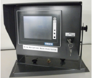
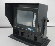
a. Main operating panel (built-in LCD touch panel, reset switch (illuminated), key switch and buzzer)
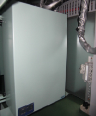
b. PLC panel
c. Power unit (built-in automatic switching circuit for AC/DC power)
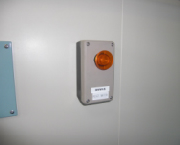
d. Reset switch (illuminated) for on-bridge equipment (WING equipment has built-in buzzer)
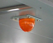
e. On-bridge equipment flash beacon
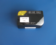
f. Captain's cabin indicator panel (if JIS standards are applied)
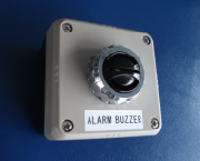
g. Buzzers for each cabin
4 Power Source
AC 100 V to 220 V (85 V to 265 V) * 2-line normal/emergency use system can be connected
DC 24 V (backup power source)
5 Power Consumption
100 W or less
6 Main Input/Output (PLC Panel Terminal Board)
Inputs
Main power source: AC 100 to 220 V ±20%
Emergency power source: DC 24 V
Automatic start signal: Remote ON signal
Emergency call input/output: OFFICER CALL(BACK-UP OFFICER)
CREW CALL
EMERGENCY CALL (OFFICER + CREW)
*Optional: Navigation light (for ships complying with MSC253 (83)) BUZZER STOP PB
*Optional: Navigation equipment: Operating signal 16-point input
Alarm signal: 16-point input
Output
Main power source error signal: N/C dry contacts
Emergency power source error signal: N/C dry contacts or
System error signal: N/C dry contacts Serial communication
Primary alarm output (Alarm audible on bridge) N/C dry contacts (NMEA signal)
Secondary alarm output (*Alarm audible in captain's cabin/room for standby officer) N/C dry contacts
Tertiary alarm output (*Alarm audible in crew room) N/C dry contacts
*Alarm to captain's cabin is according to contents of captain's call settings.
7 Optional Functions
Our system (SWAS-CP6) gives precedence to augmentability by providing the easy addition of the optional functions shown below.
a) With this function, a signal is received to verify that crew keeping watch have not fallen asleep and watch duties are being performed, and this is automatically reset so that the crew keeping watch do not have to press any buttons.
- Radar was operated.
- Engine telegraph was operated.
- Auto-pilot was operated. etc.
b) When crew keeping watch is negligent, safety is secured due to the inclusion of a function that automatically issues an alarm.
- Alarm is issued if an unidentified ship is detected within the radar guard ring.
- If a possible collision alarm is issued from the collision prevention radar.
- A function is provided so that, if the ship goes off the autopilot course, an alarm or similar signal is received, an alarm is output in the wheelhouse such that if the condition is left as is, alarms are issued to all sections throughout the ship.
Caution!
This system has been tested for the model-acquired certification according to the requirements of IEC 60945 (international rules) and has passed. It cannot be modified by anyone, especially for electro-magnetic countermeasures.
* Please contact Sanko Electric if increasing the buzzers. A power source capacity check is required.
8 Component Parts
|
Distance from magnetic compass |
||
 |
 |
 |
|
|
|
9 Accessories
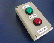
Two Types of Sounds for Buzzers Equipped to Living quarters With Buzzer Reset Switch (Equipped to wing)
|
|
|